Three-Phase Induction Motor Spin-Up
This demo extends the synchronous PM workflow to the transient, conductive case. It drives a three-phase stator with prescribed sinusoidal currents, solves the magneto-quasistatic system with the semi-implicit Crank–Nicolson wrapper, and lets a squirrel-cage-style rotor accelerate under the resulting torque. Use it to sanity-check eddy-current torque production, slip behaviour, and the interaction between the transient field solve and the RK4 mechanical integrator.
Quickstart
python3 python/gen_three_phase_induction_motor.py --profile ci --mode spinup \
  --out inputs/three_phase_induction_motor_spinup_ci.json
./build/motor_sim --scenario inputs/three_phase_induction_motor_spinup_ci.json \
  --solve --vtk-series outputs/induction_motor_spinup_ci.pvd --solver cg \
  --tol 5e-6 --max-iters 40000
python3 python/check_pm_spinup.py --mechanical outputs/induction_motor_mechanical.csv \
  --scenario inputs/three_phase_induction_motor_spinup_ci.json \
  --rotor induction_rotor --min-angle-rise 6 --min-speed-rise 6
python3 python/animate_three_phase.py --pvd outputs/induction_motor_spinup_ci.pvd \
  --scenario inputs/three_phase_induction_motor_spinup_ci.json \
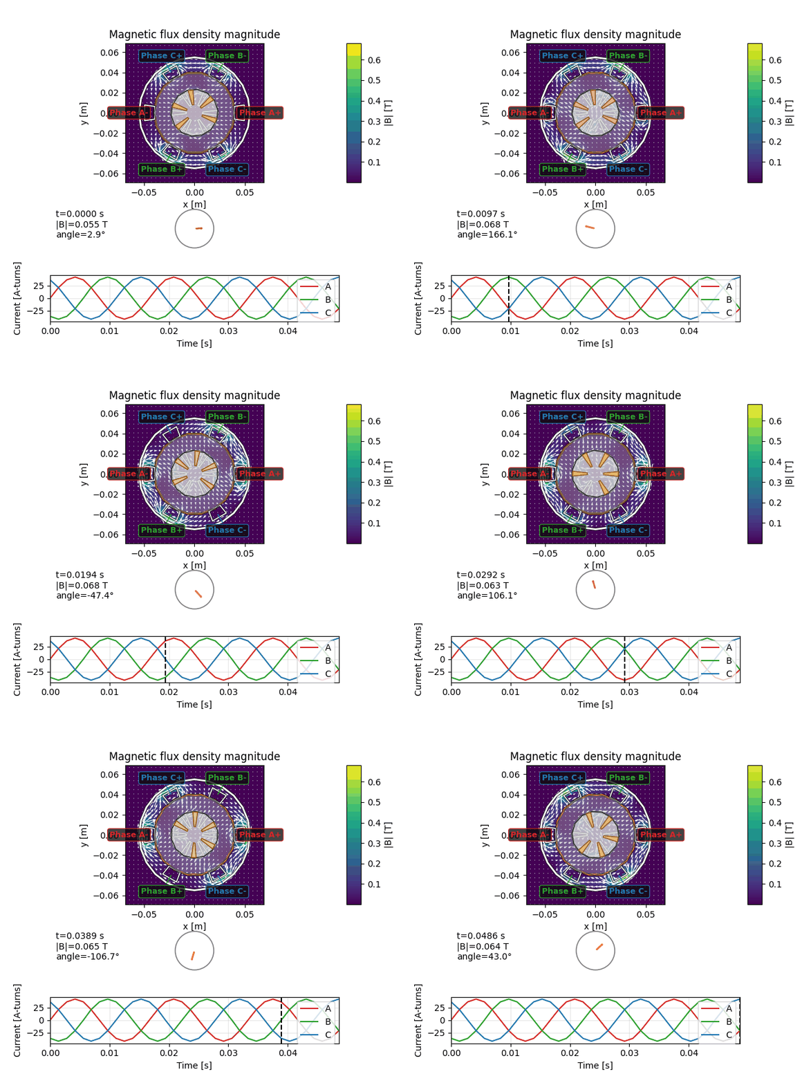
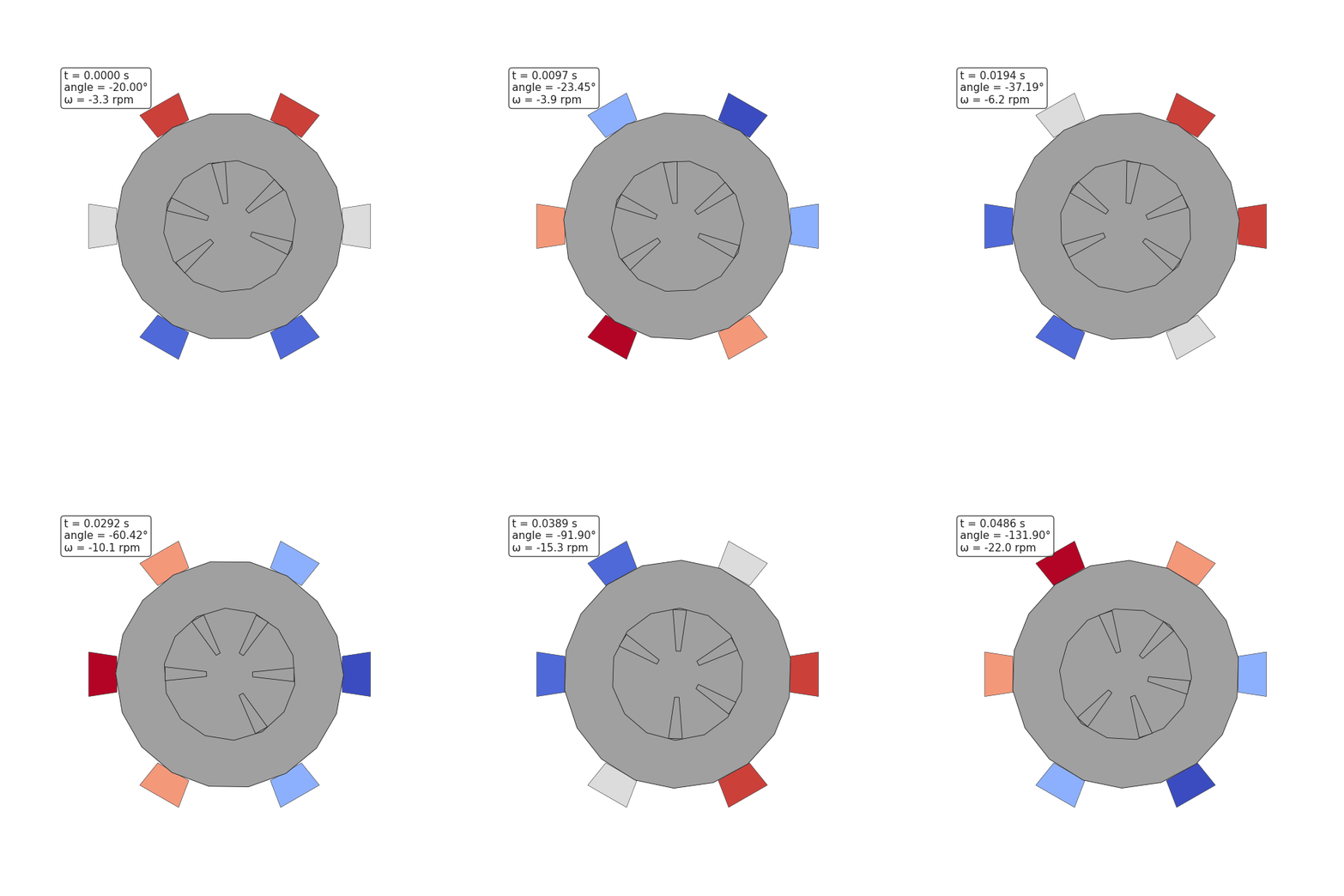
  --save induction_motor_spinup.mp4 --frame-png induction_motor_spinup.png
Unlike the PM walkthrough there are no magnets or rotor circuit links. All rotor torque comes from induced currents in the conductive bars, so the transient solver must stay enabled and the mechanical integrator consumes the torque probe output every frame.
Profiles
python/gen_three_phase_induction_motor.py ships with the familiar ci and
hires presets:
ci: 65×65 grid, 12 frames per electrical cycle, three cycles (36 frames)hires: 401×401 grid, 180 frames per cycle, six cycles (1080 frames)
Both support --cycles and --frames-per-cycle overrides. The CI profile keeps
the geometry lightweight—circles are tessellated with 24–30 points (24 for the
stator, 18 for the bore, 14 for the rotor, 30 for the torque loop) and
coordinates are rounded to four decimal places—so fixtures remain reviewable.
The generator also exposes --mode locked if you want a deterministic rotor
pose for debugging; the spin-up regression omits rotor overrides so the
mechanical simulator evolves the angle based on torque feedback.
Scenario highlights
- Rotor cage – The rotor combines a high-µ iron core with six conductive
bars (σ≈1.8×10⁷ S/m) and a modest core conductivity (σ≈5×10⁵ S/m) so eddy
currents can circulate. All rotor polygons are grouped under the named rotor
induction_rotor, letting the mechanical simulator rotate the cage as a rigid body. - Transient solve – The top-level
"transient"block requests the Crank–Nicolson wrapper with a timestep equal to one frame spacing. Each frame stores the previous vector potential so the solver can apply the \(\sigma/\Delta t\) mass term and march the field forward without rebuilding matrices. - Phase drives – Current regions still carry phase labels, turn counts (50
per slot by default), and a 0.55 fill fraction. The generator emits per-frame
"phase_currents"overrides rather than circuits, so the stator ampere-turns follow the 42 A peak sinusoids directly. - Mechanical trace – The
mechanicalsection provides inertia, damping, load torque, and ties the rotor to the torque probe. CI capturesoutputs/induction_motor_mechanical.csv, andpython/check_pm_spinup.pymeasures absolute angle/speed growth so it can validate the trace with--rotor induction_rotoreven though the rotor spins negative relative to the stator field. - Outputs – VTK series, outline polydata, bore-field CSVs, three back-EMF
probes (one per positive slot), and the mechanical trace mirror the PM demo so
ParaView workflows stay familiar. The torque probe aggregates its timeline to
induction_motor_torque.csv(withtime_s,frame_index,Fx,Fy,Tz[,CoEnergy]) so slip and torque comparisons are easy to chart without collecting each_frame_###file manually.
Regression fixture
The CI test tests/induction_spinup_test.cpp exercises the lightweight
regression stored at inputs/tests/induction_spinup_test.json, generated via:
python3 python/gen_three_phase_induction_motor.py --profile ci --mode spinup \
  --out inputs/tests/induction_spinup_test.json
Key baked-in values:
| Quantity | Value |
|---|---|
| Grid | 65×65 Cartesian cells over a 0.14 m square |
| Electrical frequency | 60 Hz (12 frames per cycle, 3 cycles) |
| Rotor inertia / damping | 1.1×10⁻³ kg·m², 8.0×10⁻⁵ N·m·s |
| Load torque | 0.08 N·m opposing rotation |
| Slot turns / fill | 50 turns per slot, 0.55 copper fill fraction |
| Rotor bars | Six wedges with σ=1.8×10⁷ S/m (core σ=5.0×10⁵ S/m) |
| Phase drive | 42 A peak prescribed sinusoids |
The regression loop calls solveTransientStep each frame, computes Maxwell
stress torque, and advances the mechanical simulator. It asserts a positive
angle and speed rise, checks the rotor remains at least 20% below synchronous
speed (2π·60 rad/s for the two-pole equivalent), and prints the slip for the
accuracy report. CI also renders the VTK series, outline polydata, and animated
field plots alongside the existing stator and PM motor artefacts.
Tips
- Keep the transient timestep aligned with the electrical frequency so the slip stays stable; extremely coarse Δt will overdamp the CN step.
- Use
--mode lockedtogether with a short timeline when debugging geometry or torque probes—this preserves the rotor pose while you focus on field snapshots. - The induction scenario currently drives phase currents directly. To co-simulate
an RL network, extend the generator with the same
circuitsschema used in the synchronous PM workflow and feed the induced back-EMF into the voltage sources. - Pair the torque CSV with the mechanical trace to estimate instantaneous slip and steady-state torque. The back-EMF probes provide an easy sanity check that induced voltages lag the stator currents as expected for an induction machine.